¶ Eltek Flatpack2
Here are the steps to configure the Eltek Flatpack2 2000W 48V HE Power Supply/Rectifier to the WatchMon supervisor.
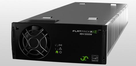
CAUTION: Not recommended for new projects, provided for legacy project support
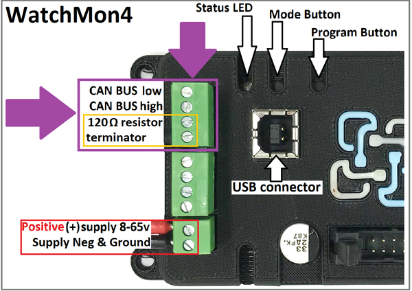
¶ Install communication cable to charger via CAN port on WatchMon.
For newer WatchMon (note 120 Ohm resistor shares CANbus High and CANbus Low
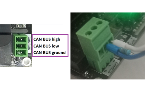
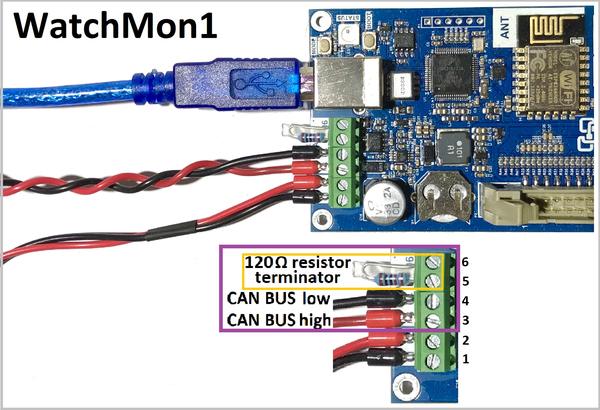
For Older Watchmon with 4 Pin CAN
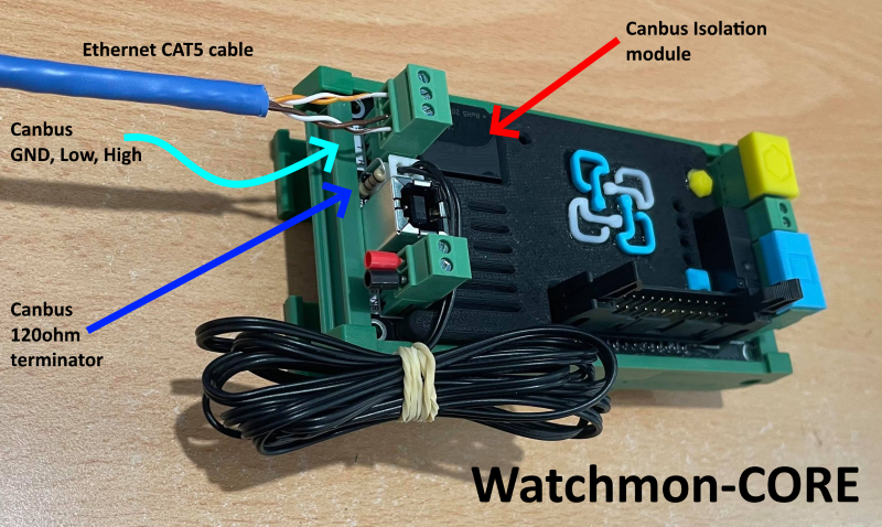
¶ Install communication cable to Flatpack2 canbus socket
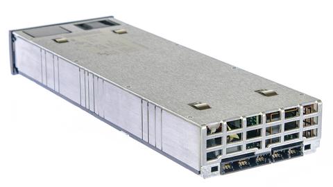
¶ 1. Initial rear view of Eltek Flatpack2 without connector socket
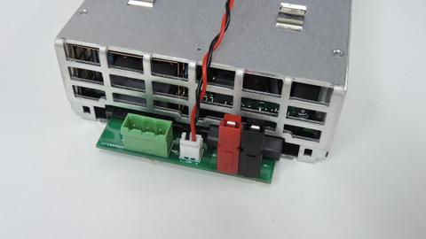
¶ 2. Install canbus communication cable with twisted (~10 per 10cm)
¶ 3. Install AC power plug
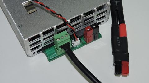
¶ 5. Install Anderson DC battery plug
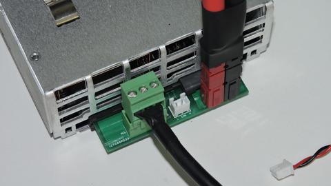
¶ 6. Install 120 canbus terminating resistor
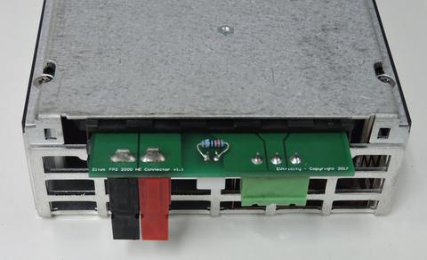
¶ 7. On bottom pcb cover the resistor and terminal pins with hot glue
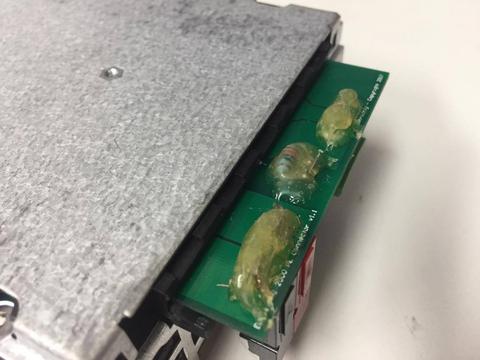
Hot glue does not substitute appropriate insulation below this pcb.
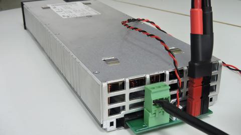
¶ 8. Finished assembly
¶ Configure Watchmon Toolkit Software
¶ 1. Integration Settings
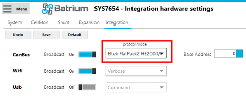
Open Watchmon toolkit and navigate to Integration Settings by clicking the Menu then Hardware and select Integration Tab.
Select Canbus protocol for Eltek "Eltek FlatPack2 HE2000/48" and Save.
¶ 2. Charging Settings
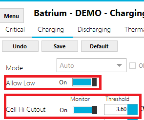
Navigate to Charging Settings by clicking the Menu then Control Logic and select Charging Tab.
Adjust the charging control logic to suit the application.

Notes:
- Low power must be enabled.
- Cell Hi Cutout should be above the CellMon bypass voltage threshold as a safe guard target.
- Low power current should suit the bypass capability of CellMon.
- When the bypass current is above Initial, it will trigger the system to low power.
- When the bypass current for all cellmons is above Final, the system will complete charging cycle.
¶ 3. Cellmon Settings
Navigate to Cellmon Settings by clicking the Menu then Hardware and select Cellmon Tab.
Adjust the CellMon Bypass Voltage, to suit the application.
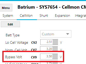
Note: Make sure to "Device Sync" the changes to the CellMons.
¶ 4. Remote Settings
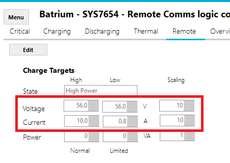
Navigate to Remote Settings by clicking the Menu then Control Logic and select Remote Tab.
Adjust the remote charging target to suit the application.
Notes:
- Scaling must be 10, for both voltage and current.
- Low power must be enabled on charging tab.
- Low power current should suit the bypass capability of CellMon.
- Charger voltage target needs to be sufficient for all cells to reach bypass threshold.
¶ 5. Live Stats
Navigate to Live Stats by clicking the Menu then Telemetry and select Live Statistics Tab.
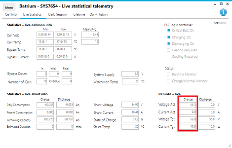
Notes:
- Scaling must be 100 for voltage.
- Scaling must be 10 for current.
- Do not run low power mode on discharging tab.
- Control logic discharge voltage cutout should match the remote target.
¶ 6. Remote Settings
Navigate to Remote Settings, to observe inverter info received.
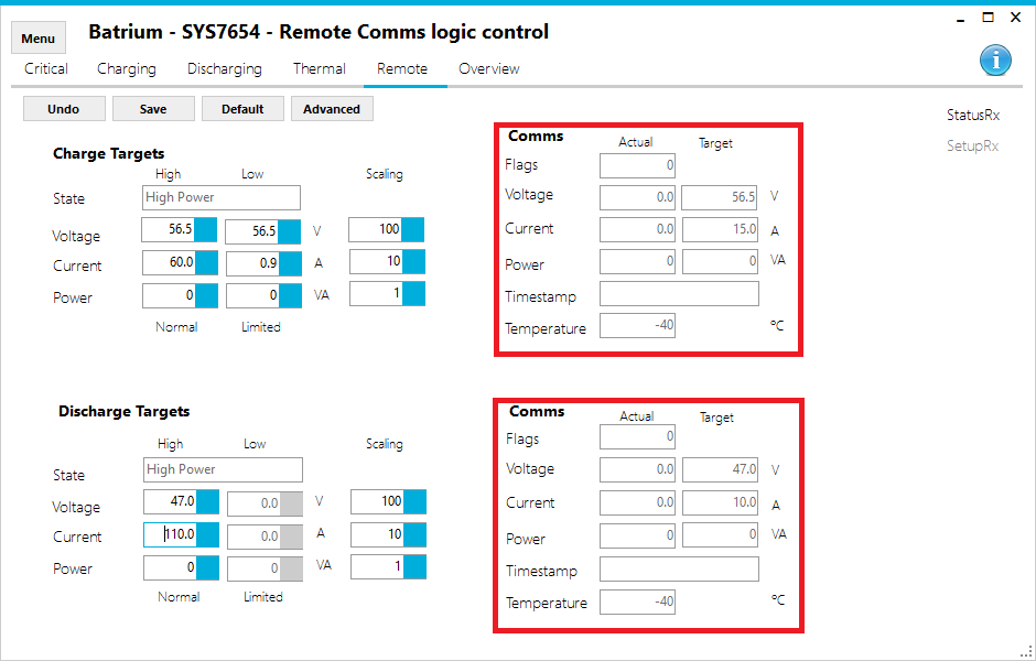
Notes:
- Charge Target Voltage - voltage cutout sent to inverter when charging
- Charge Target Current - ampere limit sent to inverter when charging
- Charge Actual Flags - reported charging mode and operating state flag received from inverter
- Charge Actual Voltage - charging cutout volatge setpoint sent from inverter
- Charge Actual Current - reported battery amperes from inverter when charging
- Charge Actual Power - reported battery state of charge SoC% received from inverter
- Charge Actual Temperature - reported battery temperature from inverter
- Discharge Target Voltage - voltage cutout sent to inverter when discharging
- Discharge Target Current - ampere limit sent to inverter when discharging
- Discharge Actual Flags - reported active message error flag received from inverter
- Discharge Actual Voltage - reported battery voltage from inverter
- Discharge Actual Current - reported battery amperes from inverter when discharging
- Discharge Actual Power - reported relay state flag received from inverter
- Discharge Actual Temperature - not used