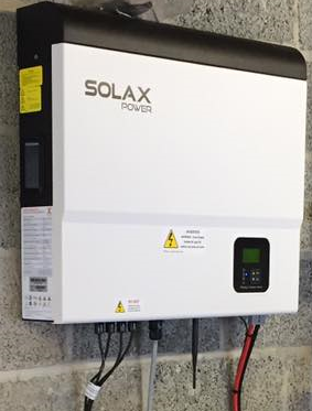
¶ SolaX Hybrid Inverter/Charger
CAUTION: PLEASE NOTE THIS METHOD IS FOR THE LOW VOLTAGE MODEL. WE HAVE HAD FEEDBACK IT DOESN'T WORK ON THE HIGH VOLTAGE MODEL.
 !
!

CAUTION: The example below has values shown for a demo LiFePO, 4 cell pack. Please ensure that you adopt the values suitable to your application and comply with the battery suppliers recommendation.
Please be advised that for a number of reasons some of our customers have switched to different inverters after their purchase.
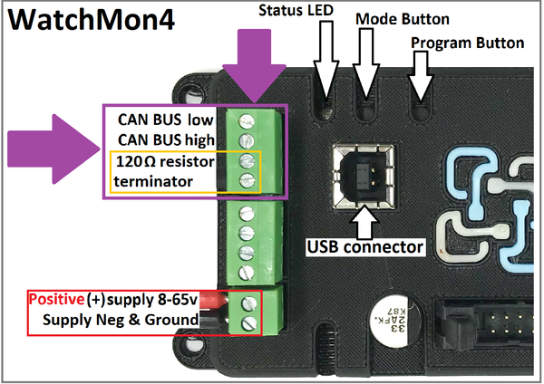
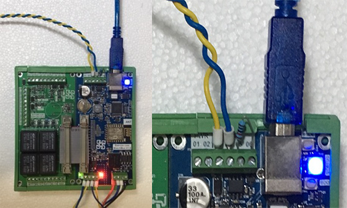
¶ Install communication cable to charger via CAN port on WatchMon.
¶ For newer WatchMon
Note: 120 Ohm resistor shares CANbus High and CANbus Low
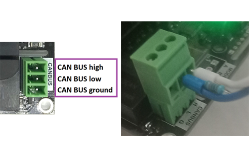
¶ For Older Watchmon with 4 Pin CAN
¶ WatchMon1
Same procedure as the WatchMon4 but the screw-terminal / connector looks different.
Add a 120 ohm terminating resistor on WatchMon Pin 5 & 6.
¶ Install communication cable to SolaX BMS Socket.
Check the version for the correct Pins to use.
(Extract from original Solax Manual)

(Extract from X1 Hybrid Solax Manual)

Typical Cat 5 cables have different colour pin combinations to the SolaX manual.

SolaX RJ45 pin 1 (typically Green/White) connects to Can-H WatchMon
SolaX RJ45 pin 2 (typically Green) connects to Can-L WatchMon
SolaX X1 Hybrid RJ45 pin 4 (typically Blue)connects to Can-H WatchMon
SolaX X1 Hybrid RJ45 pin 5(typically Blue/White) connects to Can-L WatchMon
NB: Using a CAT5 Ethernet Cable, strip back the cable and connect to the pins identified above.
¶ Configure Watchmon Toolkit Software
¶ 1. Integration Settings
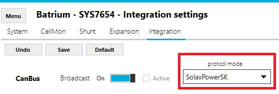
Open the WatchMon Toolkit and navigate to the Integration Settings by clicking the Menu then Hardware and select Integration Tab.

Select CANbus protocol to "SolaxPowerSK" and Save.
¶ 2. Charging Settings
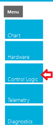
On WatchMon Toolkit, navigate to Control Logic menu, then Charging tab.
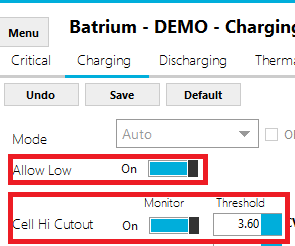
Adjust the Charging Control Logic to suit the application.

Notes:
- Low power must be enabled.
- Cell Hi Cutout should be above the CellMon bypass voltage threshold as a safe guard target.
- Low power current should suit the bypass capability of CellMon.
- When the bypass current is above Initial, it will trigger the system to low power.
- When the bypass current for all cellmons is above Final, the system will complete charging cycle.
¶ 3. CellMon Settings
Navigate to Hardware, then CellMon tab.

Adjust the CellMon Bypass Voltage, to suit the application.
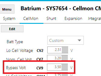
Note: Make sure to "Device Sync" the changes to the CellMons.
¶ 4. Remote Settings
Navigate to the Remote tab on the Control Logic screen.

¶ Adjust the remote charging target to suit the application.
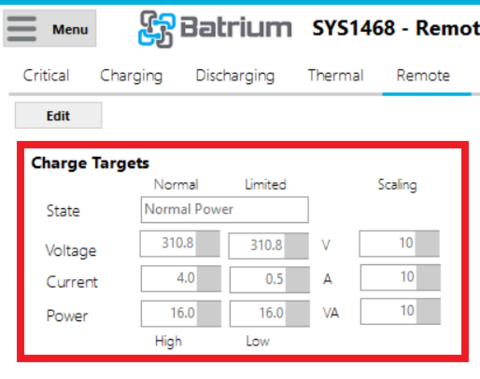
Notes:
- Scaling must be 10, for both voltage and current.
- Low power must be enabled on charging tab.
- Low power current should suit the bypass capability of CellMon.
- Charger voltage target needs to be sufficient for all cells to reach bypass threshold.
¶ Adjust the remote discharging targets to suit the application.
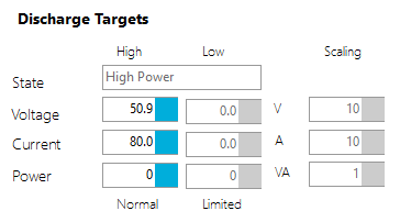
Notes:
- Scaling must be 10, for both voltage and current.
- Do not run low power mode on discharging tab.
- Control logic discharge voltage cutout should match the remote target.
¶ 5. Live Stats
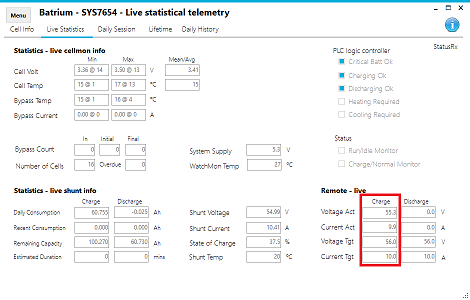
Navigate to Telemetry, then Live Stats to observe system operation.
