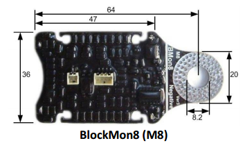
¶ BlockMon M8 Cell Monitor
Specifications are available: LongMon-BlockMon-LeafMon Data Sheet PDF
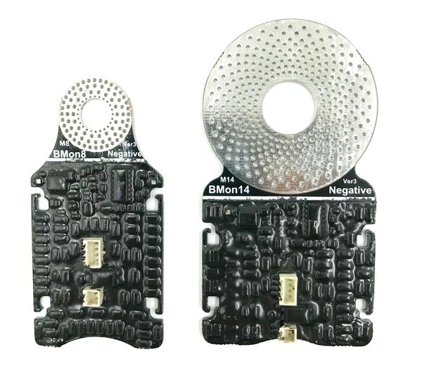
¶ Intelligent Cell Monitoring Unit
- Battery range 2.2V to 5.4V.
- Bypass current 0.00A to 2.20A (typically 1.00A).
- Over-temperature protection.
- Over-voltage protection up to ±20V.
- Noise immune opto-isolated.
- Cell temperature and bypass load temperature measurements.
- Live individual cell parameters and remote cell diagnostics.
- Sealed in black thermally conductive epoxy (robust and safe).
- Red and green LEDs for diagnostics and status.
- All parameters are fully remotely programmable and the software is remote upgradeable.
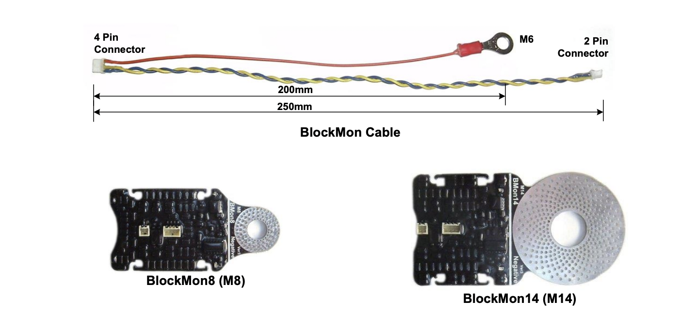
Includes cable, consider purchasing spare BlockMon cables.
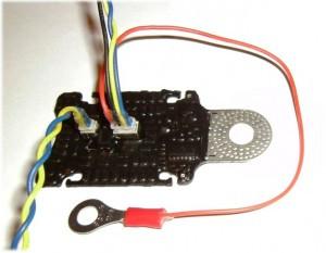
Here is an example showing the cables connected to the BlockMon:
¶ Purchase the BlockMon M8
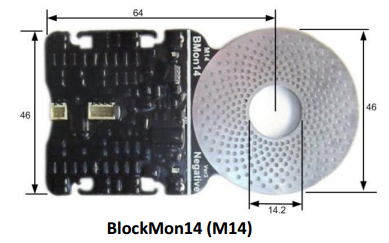
¶ BlockMon M14 Cell Monitor
- Battery range 2.2V to 5.4V.
- Bypass current 0.00A to 2.20A (typically 1.00A).
- Over-temperature protection.
- Over-voltage protection up to ±20V.
- Noise immune opto-isolated.
- Cell temperature and bypass load temperature measurements.
- Live individual cell parameters and remote cell diagnostics.
- Sealed in black thermally conductive epoxy (robust and safe).
- Red and green LEDs for diagnostics and status.
- All parameters are fully remotely programmable and the software is remote upgradeable.
¶ Connecting BlockMons
¶ Connecting the Battery Chain
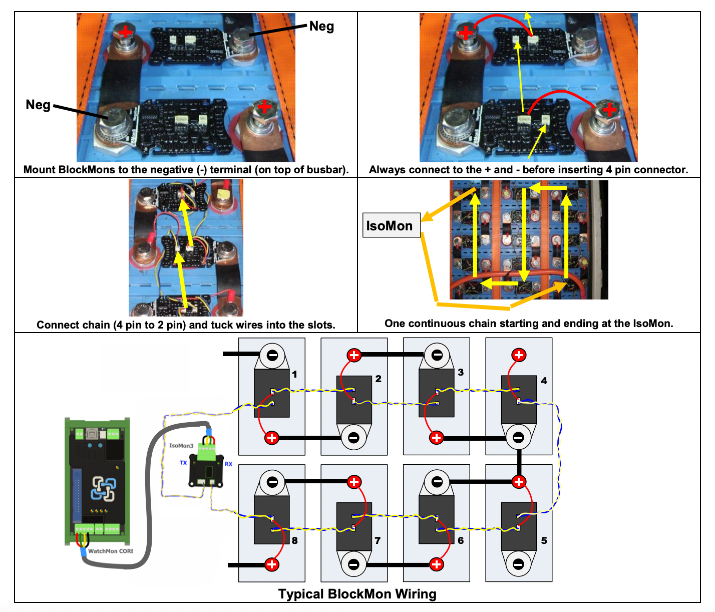
- Perform each operation with the small cable connectors unplugged from the PCB. Only connect the plug to the PCB once both terminals are secured to the cells. This reduces the chance of high-voltage damage across the input terminals of the BlockMons.
- Start with the most negative battery (cell #1) and work up the chain to the most positive.
- Secure BlockMons to the negative cell terminals. Mount them above the busbars. Do not allow the bottom electronics area (beyond the white line) to come into contact with any other metal. This area is live relative to the cell voltages.
- Connect the cable red ring terminal to the battery positive.
- Lastly, connect the small 4 pin connector. At this point, the PCB LEDs will flash. The green LED will stay ON until it has received the first valid data (from PC).
- Connect the next BlockMon. Connect the 4 pin output from the previous device to the 2 pin input of the present device to form a continuous “daisy” chain.
- As each device is mounted ensure that the green BlockMon LED is ON (the device is powered).
- It may be necessary to extend the blue and yellow twisted cables. Do this by splicing in additional lengths of twisted cables. These cables are live relative to the previous cell. Do not allow them to come into contact with other batteries or metal.
- It is not essential that the cell battery chain progresses in the same order as the cell connection order. The two-pin input at the BlockMon is optoisolated and can daisy chain to any other cell in the pack.
When installing, remember to insert the 4 pin connectors last. In the same way, always unplug the 4 pin connector first before disconnecting the battery terminals to prevent possible high voltage events damaging the BlockMons.
The red power connection for each BlockMon must be applied across one cell only. LongMons are ±20V tolerant, however, take care when wiring.
When mounting the BlockMons, do not allow metal to come in contact with the top or bottom of the PCB surface. The black thermally conductive epoxy coating adds robustness but does not provide sufficient insulation to prevent short circuit. A short to either of these surfaces will damage the BlockMon electronics.
¶ Connect the CMU to the Battery Chain
- Use the same blue and yellow twisted pair cables to terminate the BlockMon daisy chains into the CMU (from the first and last battery connections).
- The spare red cable at the CMU is not used and can be cut off or insulated.
- Plug the CMU into the WatchMon
The software feature “Network Tester” can be used to locate breaks in the chain (see Tools Menu). Renumber the cell chain (addresses) through the software commissioning wizard once the full battery chain has been completed.
¶ BlockMon Mounting Notes
The diagram below shows the typical mounting screw arrangement.
BlockMons have a strong 2mm thick PCB. However, it is possible to apply excessive bend forces on the BlockMon PCB near the temperature sensor (requiring replacement of the PCB).
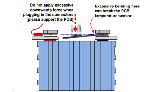
Support the PCB when inserting and removing the connectors. Note when the connectors are fully inserted there is normally a 1mm gap at the top of the connector (as shown below).

In high vibration environments, it is good practice to provide soft non-conductive support (cushion) under the BlockMons so that they do not vibrate excessively (double-sided tape, foam etc.).

¶ BlockMon Cables
¶ Why Is The Eyelet M8?
We only have one type of BlockMon cable rather than an M8 and M14 version. This is to keep volumes at reasonable levels and allow us to sell the cables at a reasonable price. What most of our customers do regarding this is to cut and spread the eyelet or cut the wire and solder it on.
The cables are the standard length shown on the webpage BlockMon.
You can extend the cables but the communication cables (blue and yellow) need to be twisted as pairs as this cuts down on noise.