¶ Wiring LeafMons
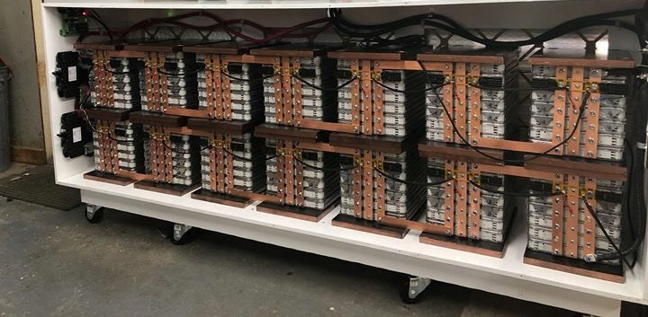
¶ Connecting the Battery Chain
- Perform each operation with the small cable connectors unplugged from the PCB. Only connect the plug to the PCB once both terminals are secured to the cells. This reduces the chance of high voltage damage across the input terminals.
- Connect busbar and earth to the centre of cells. When connecting cells in parallel these are connected using busbars.
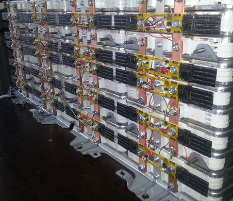
- Mount LeafMon board to the Leaf Cell making sure of correct orientation (negative (-) terminal and positive (+) terminal.
- Start with the most negative battery (cell #1) and work up the chain to the most positive. Connect chain (4 Pin to 2 Pin). One continuous chain starting and ending at the WatchMon
- At this point, the PCB LEDs will flash. The green LED will stay ON until it has received the first valid data (from WatchMon or PC).
- It may be necessary to extend the blue and yellow twisted cables. Do this by splicing in additional lengths of twisted cables. These cables are live relative to the previous cell. Do not allow them to come into contact with other batteries or metals.
¶ Connect the WatchMon to the Battery Chain
- Use the same blue and yellow twisted pair cables to terminate the daisy chains into WatchMon (from the first and last battery connections).
- Connect the Cellmon modules to the WatchMon.
The software “Network Tester" can be used to locate breaks in the chain (see Hardware menu). Re-number the cell chain (addresses) through the software commissioning wizard once the full battery chain has been completed.
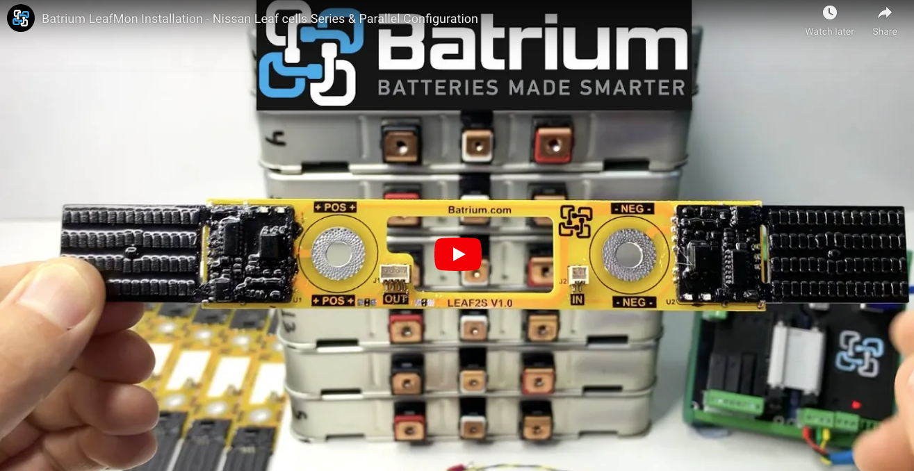
VIDEO: Batrium LeafMon Installation - Nissan Leaf Cells Series & Parallel Configuration
¶ Notes
- Carefully monitor the cell terminal polarity prior to wiring in series or parallel.
- Please Note: Modules that have low miles will perform better than cells with high miles or from climates that are Hot and/or Cold. Expect to see marks and scratches on the outer metal casing as part of wear and tear as part of the removal process.
¶ Details about the Nissan Leaf Battery Cells
¶ Nissan Leaf Gen 1 - Module
Requires 1 LeafMon to handle the 2 in a series configuration
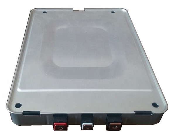
¶ Nissan Leaf Gen 2 - Module
Requires 1 LeafMon to handle the 2 in series configuration
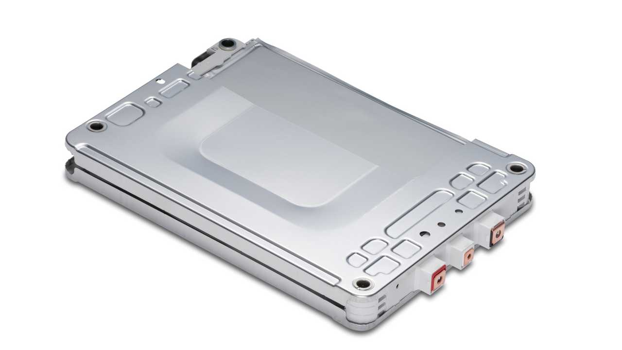
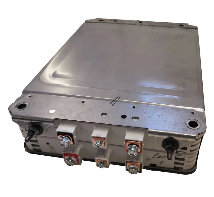
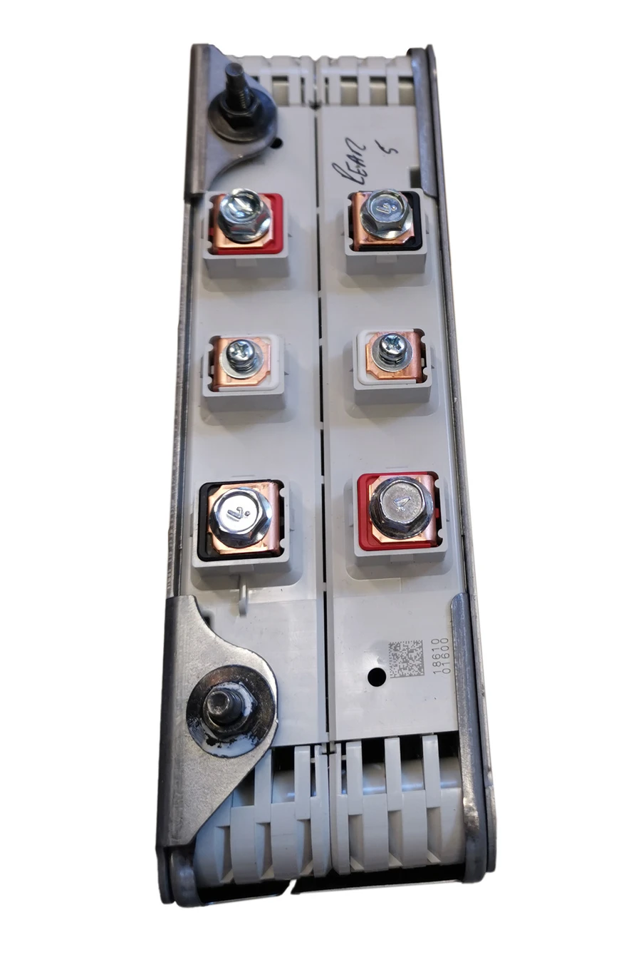
¶ Nissan Leaf Gen 4 - Module
Requires 2 LeafMon to handle the 4 in a series configuration.
Harder to reconfigure into multiple in parallel prior to being put in series.
1670Wh Module Specification Original Capacity 1670Wh
Nominal voltage 7.3V | 56Ah ( 2 in series)
Length 300mm ( 319mm over terminals)
Width 222mm
Height 68mm
Mass 8.7kg
¶ Related Links
VIDEO: Batrium LeafMon Installation - Nissan Leaf Cells Series & Parallel Configuration