¶ Balancing Algorithms
- A key job of your Batrium BMS is to balance your cells.
- You can choose how we do this depending on your chemistry and charger behaviour with three algorithms:
- The main algorithm is Top Balancing, which operates at the top of charge and is added to by:
- Timed Latch, which is good for LiFePO4 cells or inverters without CAN control, and
- Auto Level, which is good for newly commissioned packs and chemistries with linear charge curves (e.g. NMC, LTO, Sodium Ion)

¶ Top Balancing
- This is the balancing method that the "extra" modes add to

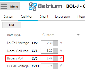
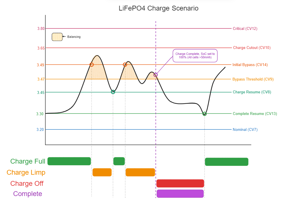
- Any time a cell goes over the Bypass Threshold (CV9), our balancing boards will bypass charging current around the cell to prevent overcharging and allow the other cells to catch up.

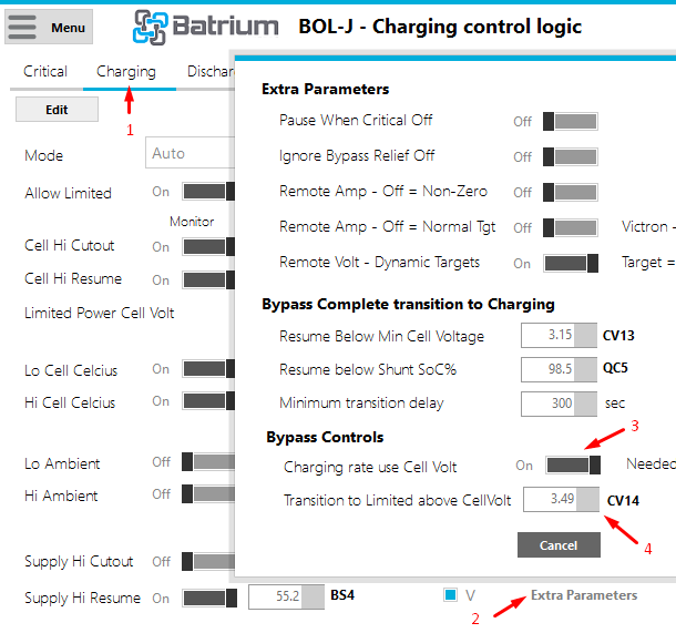
- If a cell goes over the Initial Bypass threshold (CV14) then the BMS will enter Charging Limited mode.

- If cells have self-discharge due to a defect or age, they will have less capacity in them at the end of charge (e.g. cells 1 and 2 in the balancing diagram), this algorithm will bypass the charge current for the higher cells and allow it through for the lower ones, allowing the lower cells to catch up.
¶ How this behaves in over time
- Typically we will see the cell voltage do something like this at the end of charge:

¶ Considerations
¶ 1. The thresholds mentioned above
- It is important to set these at the right value, a good starting point for LiFePO4 would be 3.47
- if you set this too high, you will be too close to the upper limits for the cell, and be stopping charge often during balancing
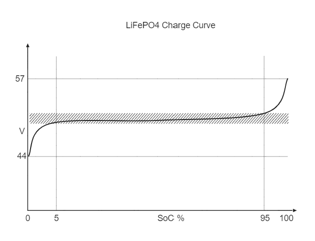
- if you set this too low, you could be balancing anywhere in the center of the charge curve, keeping in mind that the internal resistance of cells means their voltages are pushed up whilst hard charging is occuring:

- Charge targets - these should be slightly above or equal to your balancing threshold, so that the charger can actually push energy in and reach balancing.
¶ 3. Charge Current
- All cells have a small internal resistance (or large if a defect is present). This means that a large current across the cell creates a small additional voltage. For example, a brand new Grade A LiFePO4 280Ah prismatic cell charged at 1C has an additional 42mV compared to one at rest:
- This may cause cells with a defect to reach balancing voltage sooner, even if it isn't more full than the others.
- For the best balancing your balancing current should equal your charge current. In the case of a K9 this is 0.8A. You can set this as your Limited charge target current.
- If you have multiple K9s, you could set it to a multiple of 0.8, i.e. 1.6A for 2 K9s.
- This assumes no thermal relief, you will need to lower it if your K9s are enclosed and have no fans.

¶ 4. Thermal relief
- Balancing creates heat in the balancing boards, and if they get beyond the Bypass Temp Limit, balancing and charging will stop to give them a chance to cool down, This is called Thermal Relief in our software. If you find this happens a lot, you should mount fans on your K9

¶ Latched Bypass
¶ Why this is needed

- As you can see in the curve above, there is very little energy in the top 5% of the curve, but a large swing in voltage compared to the middle.
- This means that your voltages can surge up quickly at the end of charge if you are using simple on/off control (you don't have CANBUS), or if your inverter has a slow control loop.
¶ How it works
- The graph below shows a trigger-happy inverter causing the pack voltage to shoot up quickly to the point that the voltage reaches Charge Cutout (CV10) and stops charging. With just top balancing, you would need to wait until the voltage sank down again to Charge Resume (CV8), and it would take a long time to balance the pack and reach the 50mAh required to complete charge.

- Latched bypass (the blue area) means that cells balance for a configurable minimum time, even if they fall under the balancing threshold again.
¶ Auto Level
- Auto level is essentially top balancing with a threshold that gradually moves down
¶ Where this is useful
- Initial balancing for new packs
- Chemistries with linear voltage curves, where lower bypass thresholds correspond to lower states of charge.
¶ How it works

- The BMS Checks that:
- Cell Voltages are stable - the default is 15s with no voltage changes, called Cell Volt Stable Time in TK2
- Not in thermal relief - CellMons/Mates are below a default of 60C
- All cells are above Cell Volt Low Cutout - this is effectively the voltage in the cell charge curve where Auto Balance will start
- SoC is above the SoC% Low Cutout
- Shunt current is below Shunt Limit - Charge and Shunt Limit - Discharge

- If all the above are satisfied, The BMS:
- Checks the cell delta (difference between highest and lowest cell)
- If this delta is greater than Different Gap in TK2, an auto level target is set to the lowest cell, but is bound by the Bypass Banding (closer one to highest cell is chosen)
- The above step is repeated until the delta is below Different Gap
¶ A note on BlockMons
- CV14 is not used, CA1 is used instead
- Current is variable, and increases the higher the cell is over CV9
¶ Related Articles
¶ Need more help?
Book a support session if you need one-on-one help to get your system tuned to its best with us, or create a post on our forum if you have questions about the above