¶ CellMate-K9
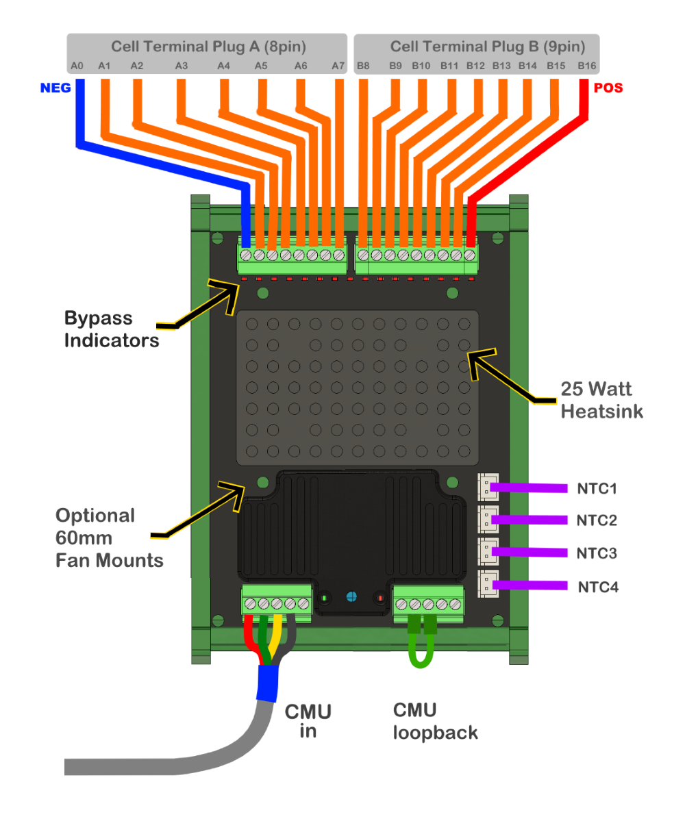
The CellMate-K9 is suitable for a shared wiring harness that can be used in conjunction with the WatchMon supervisor.
¶ Overview
- 3s to 16s enabling monitoring of 3s - 12V systems all the way to 16s 48V systems
- Two or more CellMate-K9 can be daisy-chained to create a higher-voltage battery
- Multi-string is possible using multiple CellMate-K9 (e.g. one per CellMate-K9 per 12V, 24V or 48V bank)
- Many CellMate-K9 can be daisy-chained to grow your system
- Requires the WatchMonCORE supervisor
- Separating cell monitoring from the supervisor for a more robust design solution
- Able to have a Fan mounted to enhance balancing (With mounting holes to enable the addition of a 60mm fan to boost balancing performance)
- Pluggable connectors for easy wiring
- Enable second-life use of existing balancing connectors in OEM packs like Tesla, Nissan Leaf, Chevy Volt, etc. that use "shared" wires between each cell in series (recommended to attach 3A fuse inline as close to the battery as possible to protect cabling)
- Cell monitoring from 0.50V to 5.50v with 0.001v resolution
- Configurable to suit LiFePO4, Lithium-Ion or custom chemistry
- Auto-Level (balancing) function at 500mA with activity LED on each cell
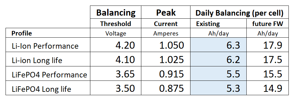
- Capable of 6 Ah/day balancing adjustment for each cell
- User-configurable presets and controls
- 4 external temperature sensors
- LEDs showing operating status and communication
- The CellMate-K9 optoisolation chip is 2500V* (*However, we do not recommend going much higher than what we have tested of 400V nominal as there are many other considerations.)
¶ What's Inside the Box
- 1 x CellMate-K9
- 1 x Din-rail holder
- 4 x Temperature sensors
- 1 x 5 pin 15cm connection cable
Optional Extras:
- 16 series TestMon to suit CellMate-K9
- Set of 18 inline 3A fuses
¶ Dimensions
- Length 107 mm x Width 86 mm
¶ Balancing Power
Cellmate-K9 is fabricated with 4 Ohm resistors to suit LiFePO4, Lithium-Ion or custom chemistry. This results in an Auto-Level (balancing) function of approximately 500mA achieving more than 6 Ah/day balancing adjustment for each cell.
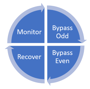
The system operates in a four-cycle sequence of 5-second intervals. This allows for approximately 50% duty cycle between adjected cells in series to not impact cell voltage sensing or exceed wiring or fuse ratings.
When balancing is required, the four stages are as follows ODDS, EVENS, resting, then sensing and repeat. Ensure that the balancing wires are dedicated to this function and do not share any circuit with other devices.
If you run other devices that need their own circuit, take time to consider the power of other equipment, like supervisors which should have their own cabling.
Be careful not to have shared wiring with adjacent CellMate-K9 from higher voltage series as these will impact each other.
¶ Charging Process
A CellMate-K9 can happily do 8Ah/day without extra fans in a well-ventilated space, to ensure the heatsink does not overheat and achieve a high value without having to wait to cool down.
Most systems need only 50 -1 50mAh/day close to the end of their life. The K9 has plenty of power for sensible service. However, the question remains if you put a cell that is full and empty together and want it to balance then the 300Ah cell difference will take 38 days = 300Ah / 8Ah/d. Most assemble their pack with the cells close to full and the system will take care of it, provided the inverter CANbus will pause the throttle and resume the charging to ensure that the BMS can take control and bring the cells into balance.
¶ Mounting a Fan
CellMate-K9 has been designed to allow a 60mm Fan to be mounted to enhance balancing performance if the customer desires.
*Note that a fan is not supplied when ordering.
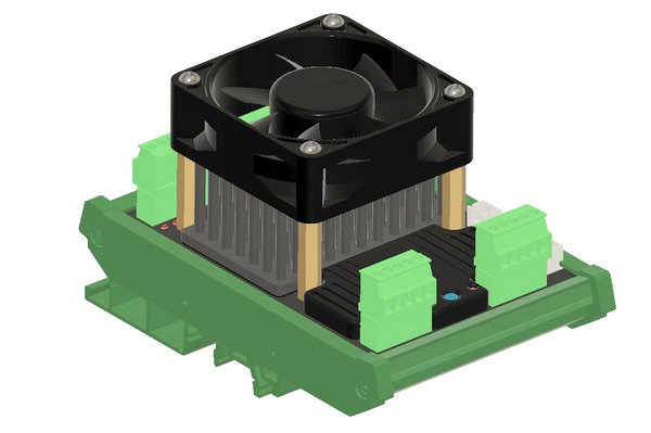
- M3 screws to mount Hex standoffs to the CellMate-K9
- Standoffs should be 30mm in order to clear the heat sink.
- Fan hole centres are 60mm apart.
- Fan power can be triggered by the logic of the WatchMon CORE
- Adopt any of the Relay/SSR to switch the fan power ON.
- Fan selection and voltage is you decision (i.e. 12, 24, 48, 5V etc).
- The fan's speed only needs a light breeze (small airflow), not a gale (high breeze). Do not run a high-volume airflow fan it will not help, will be noisy, shorter lifespan and waste power. The smaller the better. With just a light breeze the temperature will drop from 60ºC to less than 10ºC above ambient when running.
- Always consider where the heated airflow is sent as capable of more than 20W combined. If within an enclosed box containing the battery cells, this heat may be desirable or not, either way, consider where the air vents are.
- Fan power of 5V must not be powered from the onboard 5V DC-DC of the WatchMon CORE
- Except for the initial commissioning (combining cells), the balancing should not be operating for an extended period of time except if cells have no defects.
¶ Cable Specification

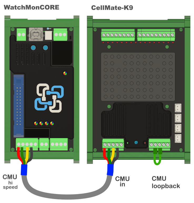
Cable joins the CellMate-K9 to WatchMonCORE and/or CellMate-K9 to additional CellMate-K9s in a daisy chain with a terminator on the last CellMate-K9 in the daisy chain.
The 5th wire (brown) is optional and is there for future functionality and as an alert pin. When this function becomes available, it will be an optional switch to detect the alert pin from the supervisor.
.png)
If you want to use a different cable, other than the one we provide:
It is OK to use the CAT5 network pair (This has 4 twisted pairs. Make sure to use multi-strand patch lead, not the in-wall solid core variant.) **Shielding is generally not required.
¶ Temperature Sensor on the CellMate-K9
¶ Configuring the Temperature Sensor
For the temperature sensors to work, you need to plug in the temperature sensors on all 4 of them. And use the all the NTC we have provided. You cannot just use 2 as it needs all 4 for each cell to have a defined value.
*For reference, the NTC is 10K with a characteristic of B3950. And the connector is a 2-pin JST-XH 2.54 mm.
As an example:
- For Cell 1-4 — Temperature Sensor 1
- Cell 5-8 — Temperature Sensor 2
- Cell 9-12 — Temperature Sensor 3
- Cell 13-16 — Temperature Sensor 4
Please know that the assignment slightly adjusts depending on the number of cells.
If for example there are only 8 cells, it may be configured as follows:
- For Cell 1-2 — Temperature Sensor 1
- Cell 3-4 — Temperature Sensor 2
- Cell 5-6 — Temperature Sensor 3
- Cell 7-8 — Temperature Sensor4
¶ Purchase the CellMate-K9
¶ Communication Network for Single CellMate-K9
¶ Communication Network for Multiple CellMate-K9
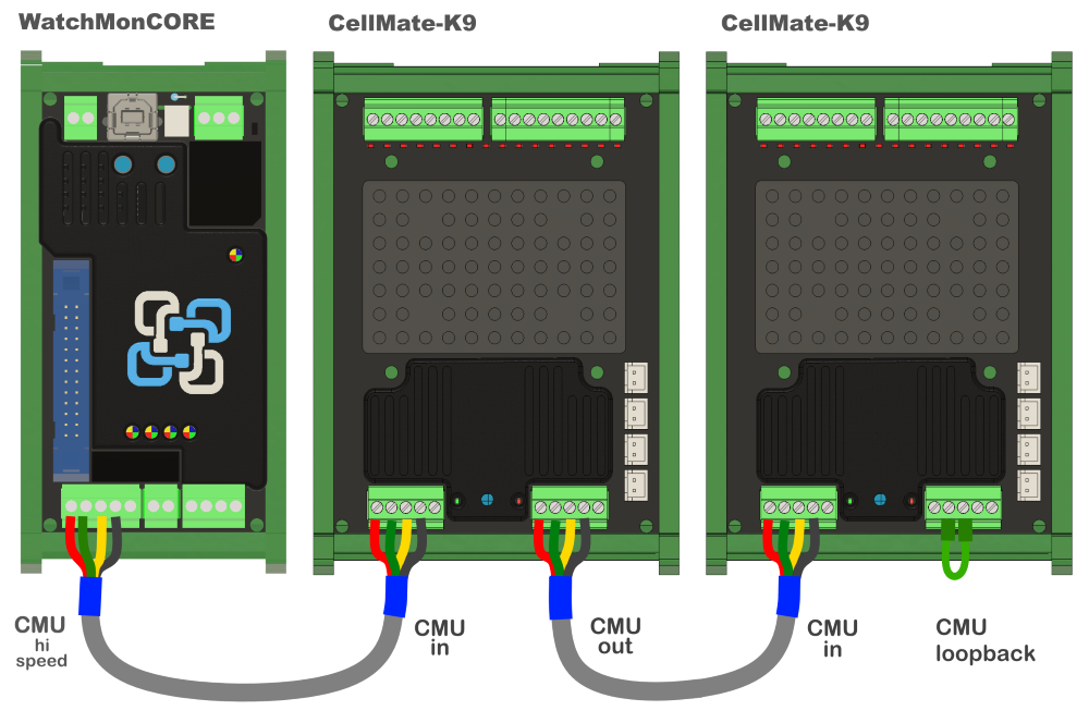
Adopt twin twisted pair cable with sufficient core to ensure no voltage drop 22-26AWG tinned and multi-strand. The cell can be in series, parallel or multi-string as each cell monitoring module is fully isolated from the CMU port. Relocate the loop back to the end of the network.
Maximum length of cable to connect two or more CellMate-K9 together? We have tested to 10m total length combining all sections, beyond this is experimental and we cannot advise further.
If you want to use a different cable, other than the one we provide:
It is OK to use the CAT5 network pair (This has 4 twisted pairs. Make sure to use multi-strand patch lead, not the in-wall solid core variant.) **Shielding is generally not required.
¶ Need extra 5V power to the supervisor?
For extra 5V power to the supervisor, with a supply above 30Vdc (i.e. 48V battery pack voltage), we highly recommend always connecting to an isolated DC-DC (ideally 24Vdc). This power can be injected into the CMU port pin for 5V and GND for the CellMate-K9, and ensure that the CMU ground pin to the supervisor is connected for the communication to work.
Consider the following booster power to run the system:
- Isolated DIN Rail Mount DC/DC Converter, Railway, 4:1, 15 W, 1 Output, 5 V, 3 A
- Input Voltage DC Min 18V Input Voltage DC Max 75V
*This should be enough as the CellMate-K9 consumes 40mA (5V 6-8mA each).
Note: Each cable can be 1.5m, capable of up to 20 x CellMate-K9 monitoring modules for a CMU network. However, will require external 5v power beyond 6 units.
For reference, see the 4 options below. This should get added, typically we see people adopt either option 3 or 4.
Know that the 5V will replace the need to provide power to the WMC supply 2 pins.
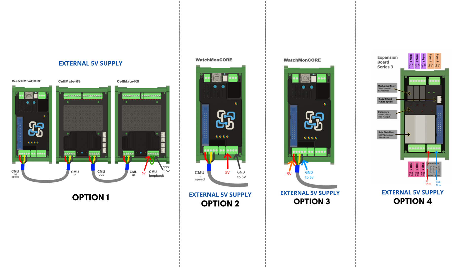
A few points to remember:
- Each K9 consumes 4mA @ 5V
- The WMC supervisor will need typically 340mA and can go higher when communicating.
- Recommended a min of 1A isolated 5V supply.
- You will only need 1 for the entire BMS system, not 1 for each unit.
See > Wiring diagram for multiple CellMate-K9s
¶ Wiring from the Battery - Fused at Cell [NOT BMS]
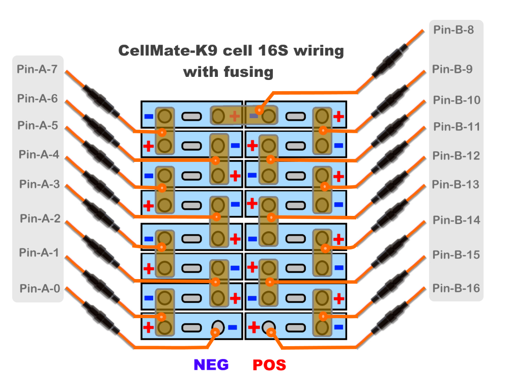
Note: Ensure fusing within 15cm of the cell terminal or closer if possible. Ensure the wiring gauge is appropriate and avoid using over-rated cables. Consider putting it into a protective cover when combining multiple cables.
We typically recommend hooking up your typical 22-26 AWG hook-up cable to an in-line 3A fuse (preferably ceramic sand-filled) to extinguish the DC arc.
Read more: Battery Cabling and Wiring Best Practices
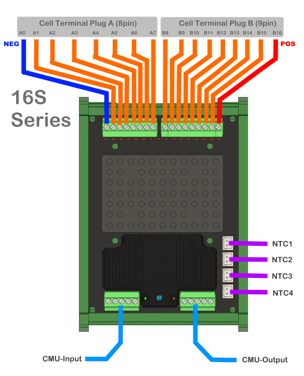
¶ Cell Terminals on CellMate-K9 for 16 Cells in Series
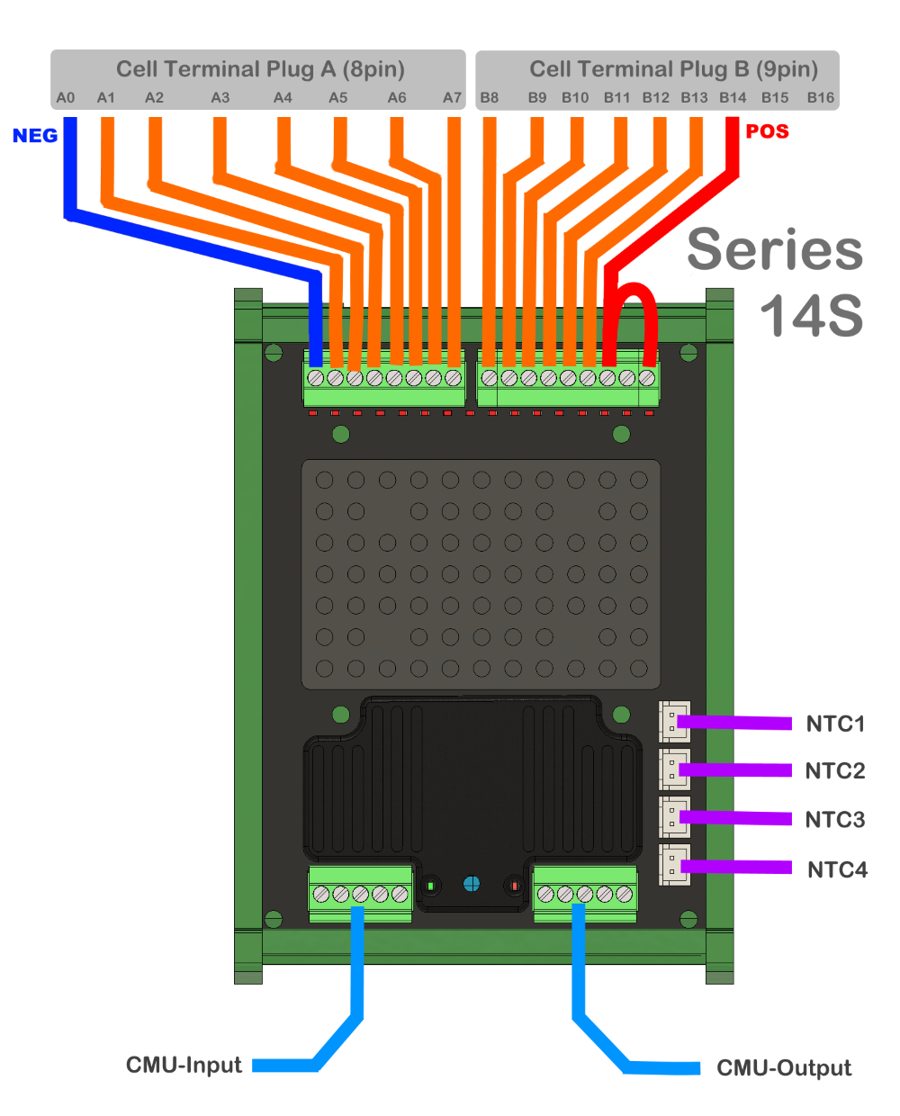
¶ Cell Terminals on CellMate-K9 for 14 Cells in Series
¶ Cell Terminals on CellMate-K9 for 12 Cells in Series

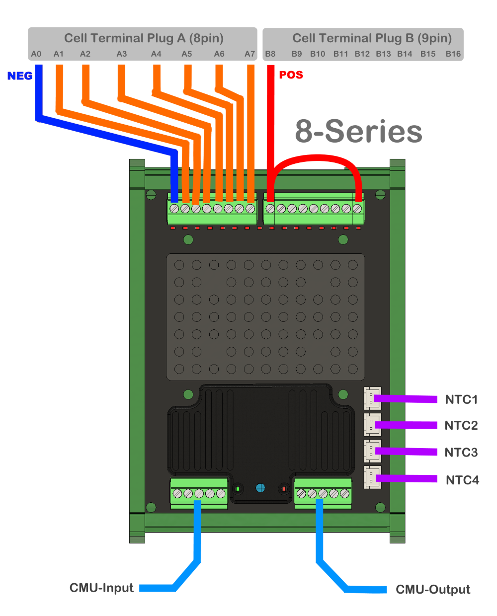
¶ Cell Terminals on CellMate-K9 for 8 Cells in Series
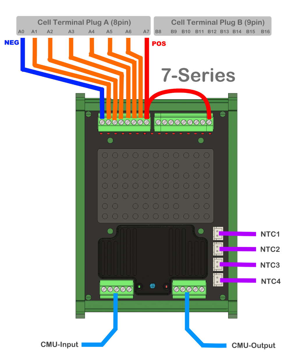
¶ Cell Terminals on CellMate-K9 for 7 Cells in Series
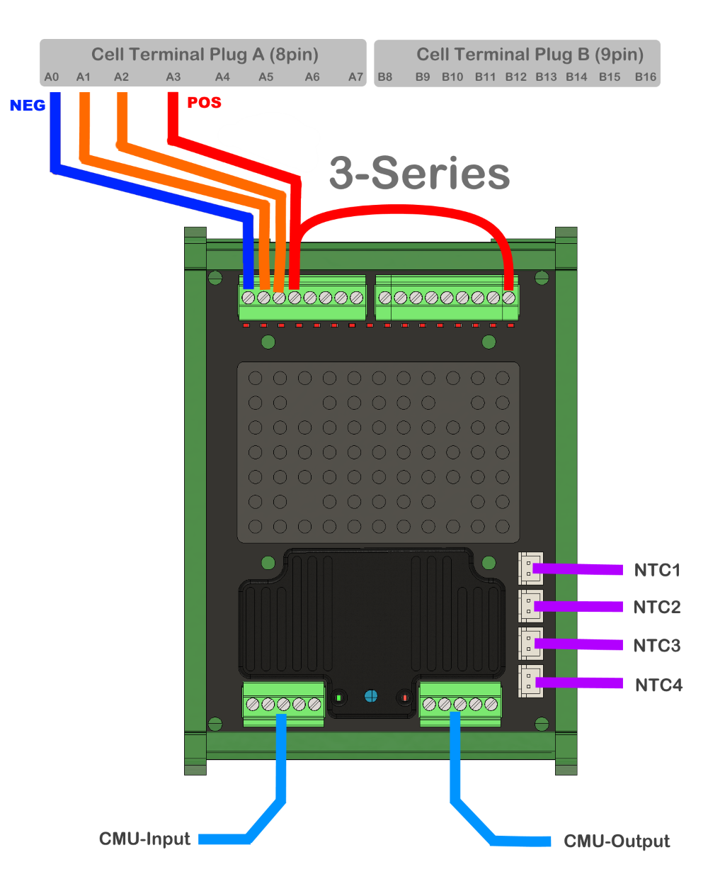
¶ Cell Terminals on CellMate-K9 for 3 Cells in Series
¶ Wiring Diagram for Multiple CellMate-K9
Remember: When wiring multiple CellMate-K9s, you need to treat each as an independent pack so that both the positive and negative of each module go direct to the cells. They cannot have a shared wire from one module to the next, nor drop the negative and only run one of the two.
Each needs to match your cells as they are built for example if in groups of 8 or something else. Ideally, each should be approximately the same voltage, with roughly the same number of cells in series, and not just have the last monitor a couple of cells.

¶ Troubleshooting the K9s
If experiencing the different troubleshooting scenarios for the CellMate-K9 such as:
- Stable but showing readings that don't match the multimeter
- Not communicating
- Occasional voltage spikes when balancing or even when not balancing
Go to the following article links:
- Fuses Resistance / Impedance
- Active Balancer on the K9s
- Troubleshooting Multiple K9s
- Do a device sync if some cells are not showing up.