¶ Victron GX
If you are looking to feed into the grid, please see our page on Victron DVCC
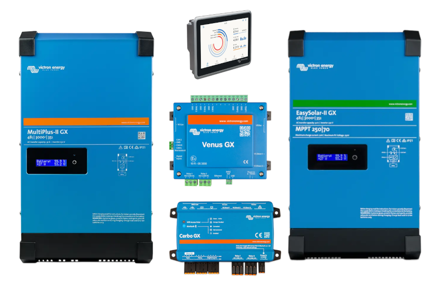
We are compatible with all Victron GX devices.
- Ekrano GX
- Cerbo GX
- Cerbo GX S *
- Victron Color Control GX - CCGX
- Victron Venus GX
- MultiPlus-II GX (built-in) *
- EasySolar-II GX (built-in) *
Products with an asterisk (*) only have a single CAN interface. If you are using other Victron devices that are running at 250kbps (e.g. solar chargers) over VE.Can, you must make sure you pick our 250kbps Victron profile Reserved 13.
¶ Step 1: Update all devices
- Ensure your ToolKit2 software is up to date: Software Updates
- Update the firmware on your WatchMonCORE: Firmware Update
- Update the Firmware on your GX: https://www.victronenergy.com/media/pg/Cerbo_GX/en/firmware-updates.html
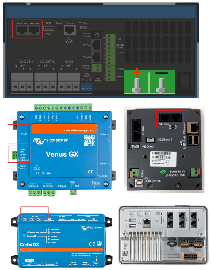
¶ Step 2: Install the CAN cable between your GX and the WatchMon
The procedure is similar for all GX devices, but the exact location of the port will vary. We suggest:
- Mount your GX and WatchMon devies
- Use an off-the-shelf Ethernet cable longer than you need to get to your GX from the WatchMon.
- If you decide to make up a custom cable yourself, use the a proper RJ45 crimper, and a RJ45 male connector.
- It is a good idea to label both ends of this cable.
- Plug in the GX side with the RJ45 plug and manage the cable as you see fit to get it to the WatchMon. You may need a terminator on the GX end, refer to your GX manual.
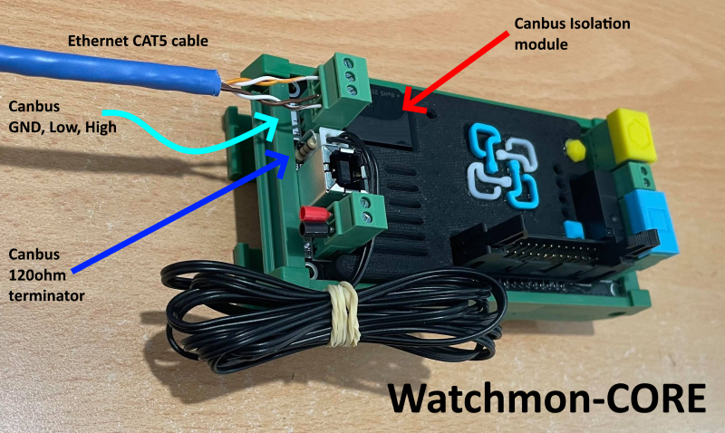
- Trim the cable at the WatchMon end leaving some extra, and strip out the wires according to the table below.
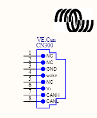
Custom Cable Pinout for Victron GX devices
| Function | VE.Can RJ-45 | Watchmon |
|---|---|---|
| GND | Pin 3 | Supply negative / ground |
| CAN-L | Pin 8 | CAN low |
| CAN-H | Pin 7 | CAN high |
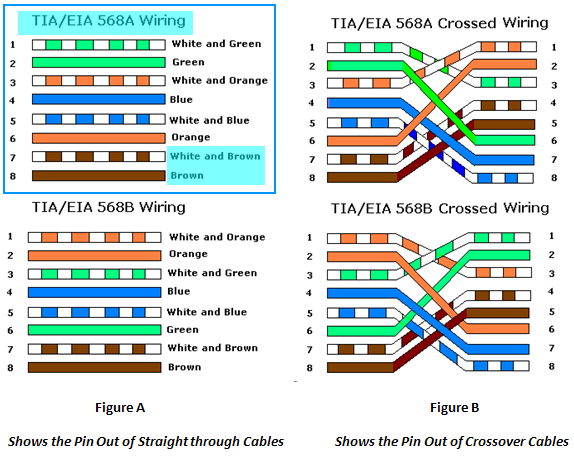
For reference, here’s an Ethernet plug diagram. Be aware that some Ethernet Cables may vary as there are two (2) common wiring colour standards. Make sure that you inspect the plug on the Victron side and follow the wiring colour to the BMS terminal.
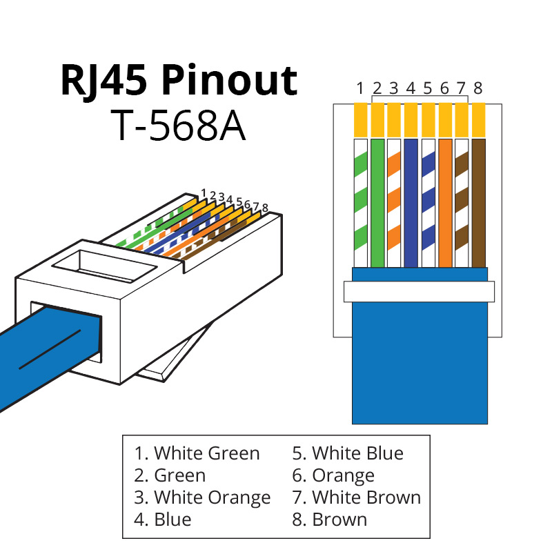
If you are making up a custom Ethernet Cable for the GX, you should use a proper crimper and fresh RJ45 male connectors.
VE.Can to CAN-bus BMS Cables Manual
Outline above is for the TIA/EIA T568A straight-though connector outlined in blue below.
¶ Install communication cable to CAN port on WatchMon.
¶ Configure Watchmon Toolkit Software
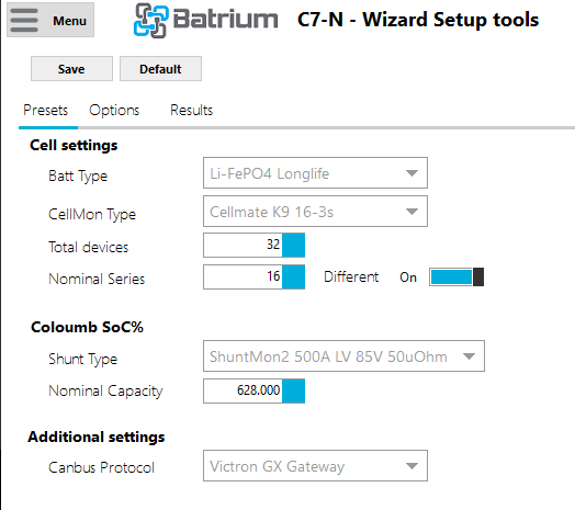
- Open the main menu in the top-left, then click the Tools button, then Wizard Setup. Alternatively, use the Wizard Setup icon in the setup checklist on the main screen:

- Configure the wizard as needed
- Select your chemistry (LongLife presets recommended)
- Select your cell monitor
- Select the total number of cells to be monitored
- Select the nominal series if different (i.e. two strings of 16S, 32 cells total)
- Select your shunt model
- Select the Ah of your cells in parallel. i.e. for two strings of 16S, choose your cell Ah x 2
- Select Victron GX Gateway as your Canbus Protocol if the WatchMon is alone in the CAN network (not sharing with Victron devices, and thus can run at 500kbps). Select Reserved 13 if the WatchMon is sharing the CAN network with Victron devices that need to run at 250kbps.
- Click Save
- Enter your device's PIN Code if prompted (written on back of WatchMonCORE unless changed)
- Wait for the wizard to complete.
¶ Victron Software Configuration
Using your touch display or Remote Console via VRM
¶ Configure your GX CAN port to match your WatchMonCORE
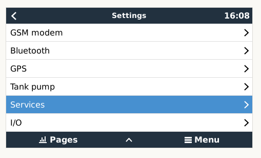
- Navigate to Settings
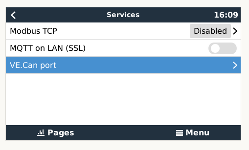
- Navigate to Services
- Navigate to VE.Can port (note this may appear as multiple entries if your GX has multiple CAN ports)
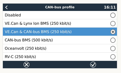
- Navigate to CAN-bus profile
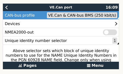
- Select the appropriate CAN profile. If you are sharing the bus with other VE.Can devices, you must to select Ve.Can & CAN-bus BMS (250 kbit/s). If you are only connecting Batrium to this CAN port, you must select CAN-bus BMS (500 kbit/s). This must also match the profile selected within ToolKit2. Either Victron GX Gateway if at 500kbps, or Reserved 13 if at 250kbps. If the profiles do not match, all devices on the bus will not work.
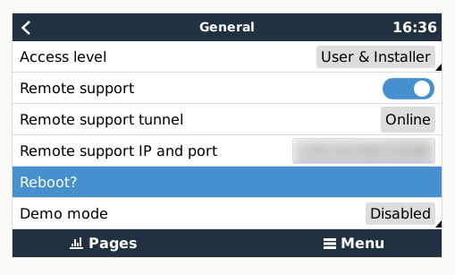
- Reboot your GX (Settings > General > Reboot?)
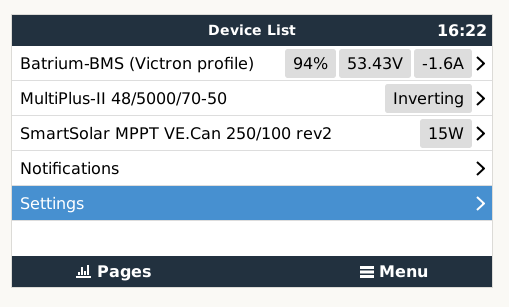
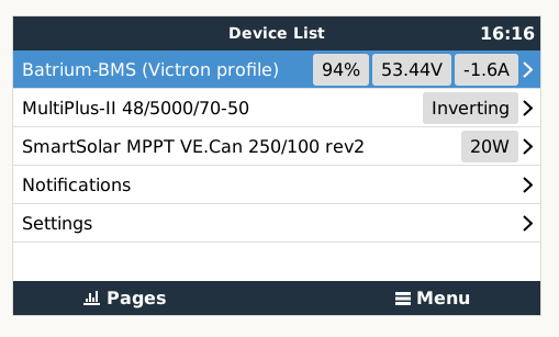
- Confirm you see Batrium-BMS (Victron profile) on the main screen (device list)
¶ Check DVCC is enabled
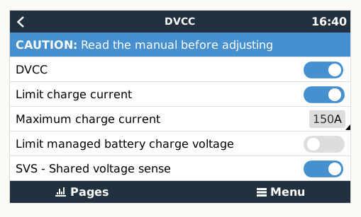
For more info on DVCC, see Victron DVCC.
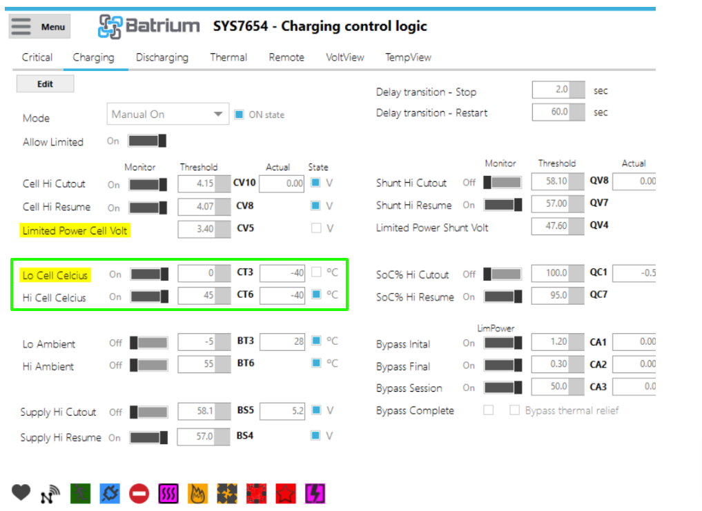
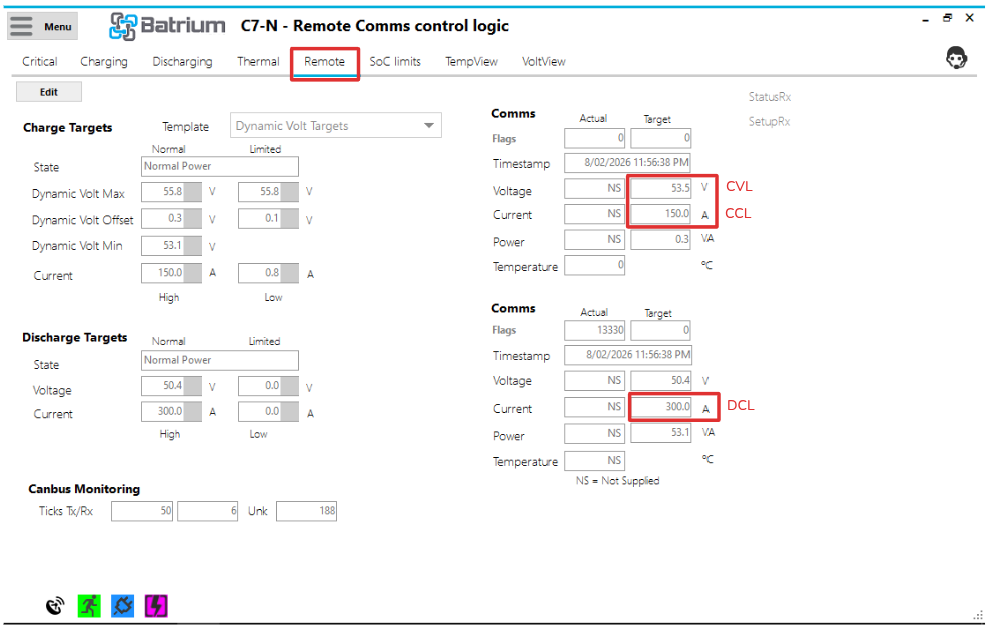
¶ Verify CCL, CVL, DCL
- Within VRM, enter the advanced area, and check that the BMS Charge and Discharge limits are being recieved by Victron.
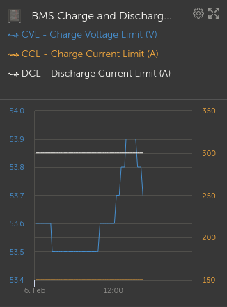
- Within ToolKit2 go to the Control Logic > Remote tab, and verify that the limits match those seen in VRM
¶ Frequently Asked Questions
¶ Can the BMS send the SoC% to the Victron Inverter?
Yes.
¶ Can the BMS send the cell statistics of the Highest and Lowest cells?
Yes, when using the Victron CANbus profile (from software release 2.16 onwards).
¶ Can the BMS ramp down the charging rate towards Full or Empty?
Yes. Adopt the correct Control Remote configuration (from software release 2.17 onwards).
¶ Why do the Remote Actuals only show NS and not values from the Victron equipment?
Not all the Victron products transmit back the optional actual values. Hence we cannot display these values if they are not transmitted from the GX.
The communication is not at fault, verify that the GX is sending the heartbeat RX timestamp to confirm communication is functioning properly.
¶ Can the BMS read the SoC% from Victron equipment instead of our own ShuntMon module?
¶ Can you run both a Batrium ShuntMon and a Victron Shunt in a series?
Yes, if desired. Several customers have chosen to install both shunts in series, which is not ideal.
¶ Can you run without a Batrium ShuntMon?
Yes, however, will limit the functionality since the BMS does not know the SoC% and cannot adjust its recommended charge and discharge targets.
¶ SoC% is not being reported correctly to Victron
Please know that this is deliberate. The BMS will limit the value it transmits to the inverter to 99% and not 100 until the charge is complete. This is because we want the inverter to continue to charge to allow the batteries to balance up to the threshold.
When complete, it transmits 100%. The system will also limit to 100% even if it exceeds this value so that internally, the BMS can recalibrate when all balancing has been completed.
¶ BMS Alert Warnings to Victron
Warnings from Victron might be triggered when these parameters are turned on:
| Warning | Condition |
|---|---|
| Battery High Voltage Warning | If you enable critical > Cell Volt High |
| Battery Low Voltage Warning | If you enable critical > Cell Volt Low |
| Battery High Temperature Warning | If you enable critical > Cell Temperature High |
| Battery Low Temperature Warning | If you enable critical > Cell Temperature Low |
| Battery High Temperature Charge Warning | If you enable charge > Cell Temperature High |
| Battery Low Temperature Charge Warning | If you enable charge > Cell Temperature Low |
| Battery High Current Warning | If you enable critical > Shunt Charge Amp High |
| Battery High Charge Current Warning | If you enable critical > Shunt Charge Amp High (same rule) |
| BMS Internal Warning | No communication was established with the BMS |
| System Status (Online/Offline) | Is Critical Batt Ok status |
.png)